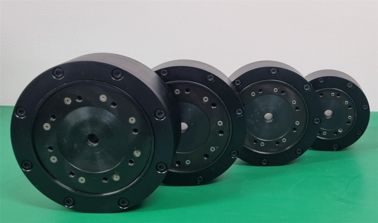
CCR-series

CCR-series
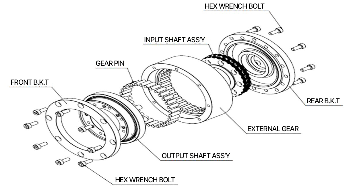
CCR series Structure

The CSR series is a cycloidal reducer that transmits rotation and torque from the input shaft through cycloidal gears, leading to a reduction in speed and an increase in torque at the output shaft. It is a high-precision, high-rigidity reducer designed for motors.
CCR series Features
It has excellent durability as a reducer using a cycloidal tooth profile.
The even engagement of the gear plate and pins ensures good rotational contact and high efficiency.
Structurally robust, it is resistant to impacts, has higher durability compared to other reducers, and operates with low noise, making it easy to use.
By minimizing the tolerances of each component, it achieves high precision with low backlash.
Reduction ratio and rotation direction
|
When the input shaft rotates and the output shaft rotates (body fixed) |
|
|
Reduction gear ratio ( I ) |
-1/R |
|
Sense of rotation |
The rotation direction of the input shaft and the output shaft are opposite |
|
When the input shaft rotates and the body rotates |
|
|
Reduction gear ratio ( I ) |
1/R+1 |
|
Sense of rotation |
Same as the rotation direction of the input shaft |
* For example, a reducer with a gear ratio of 30:1 has a gear ratio of 30 when the output shaft rotates (with the body fixed), and a gear ratio of 31 when the body rotates.
Performance Table
Please slide the table to check.
| Model | CCR04 series | CCR05 series | |||||
|---|---|---|---|---|---|---|---|
| Reduction gear ratio | 30 | 40 | 50 | 30 | 40 | 50 | |
| Rated Allowable Torque | N.m | 28 | 38 | 47 | 35 | 40 | 58 |
| Peak Maximum Torque | N.m | 60 | 80 | 95 | 75 | 105 | 120 |
| Allowable Input Speed | rpm | 3100 | 3100 | ||||
| Maximum Input Speed | rpm | 3800 | 3800 | ||||
| Backlash | arcmin | ||||||
| Recommended Motor Capacity | W | 120 | 120 | ||||
| Input Shaft Moment of Inertia | x 10-3 Kg.㎡ | 0.135 | 0.552 | 0.753 | 0.235 | 0.596 | 1.019 |
| Input Shaft Diameter | mm | Ø8.0 | Ø10.0 | Ø12.0 | Ø8.0 | Ø10.0 | Ø12.0 |
| Reducer Weight | Kg | 1.1 | 1.7 | 2.0 | 1.7 | 2.4 | 3.0 |
1) The input shaft hole diameter ranges from Ø8.0 to Ø12.0 and may vary based on user requirements.
2) The keyway for the input shaft hole diameter will also be determined in consultation with the user (KS regulations will apply in the absence of special requirements).
3) Please refer to the product outline and related dimensions.
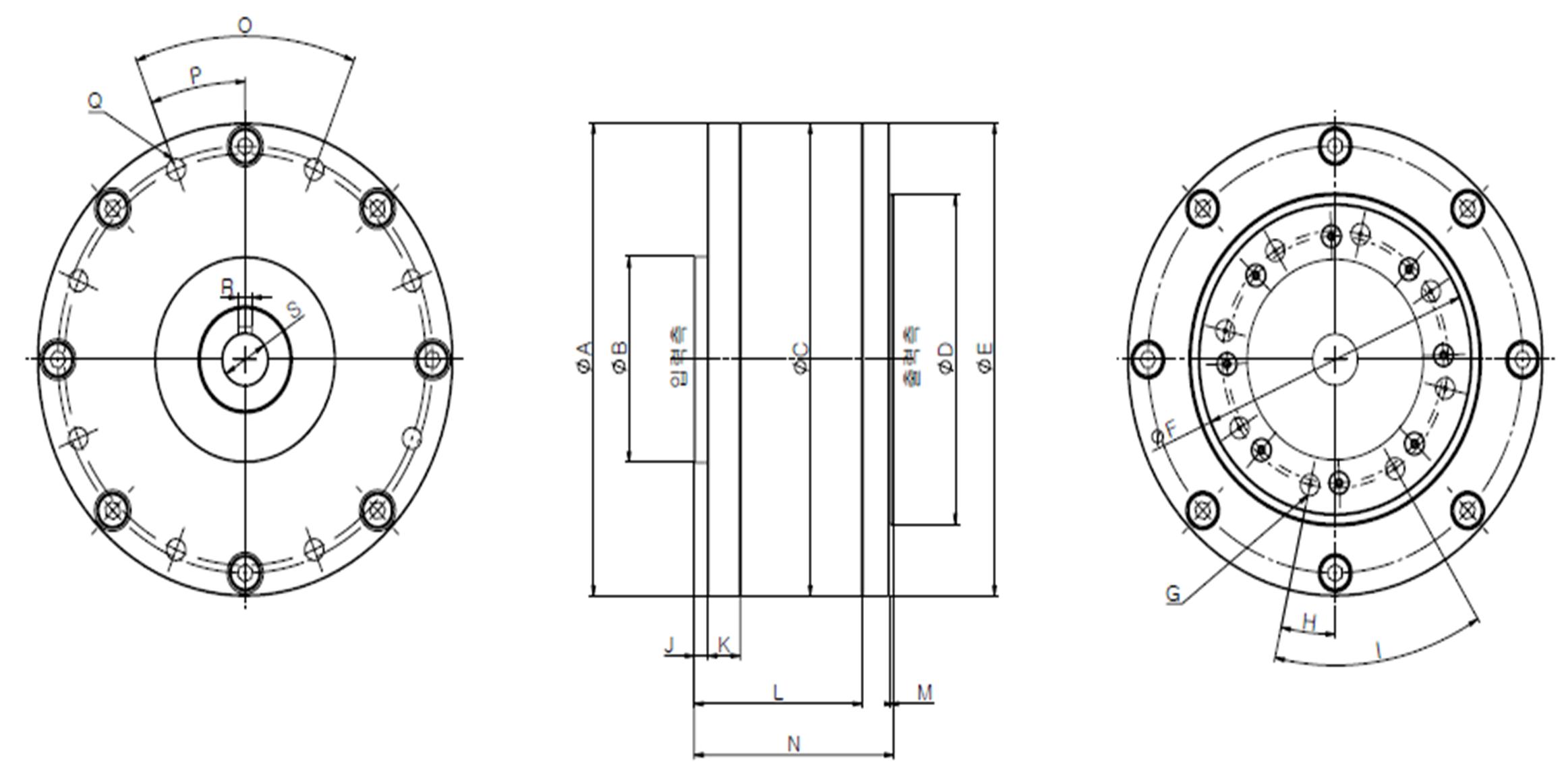
Product Appearance and Related Dimensions
1) CCR04 series

Please slide the table to check.
| reduction gear ratio | ØA-0.1/-0.2 | ØB-0.009/-0.025 | ØC0/-0.022 | ØD | ØE-0.1/-0.2 | ØF+0.030/0 depth 3 |
|---|---|---|---|---|---|---|
| 30 | 92 | 55 | 92 | 64 | 92 | 64 |
| 40 | 112 | 55 | 112 | 84 | 113 | 80 |
| 50 | 122 | 55 | 122 | 94 | 122 | 90 |
| G | H | I | J | K | L | M | N |
|---|---|---|---|---|---|---|---|
| 8-M5, PCD Ø50 | 12.94° | 45° | 3 | 7.2 | 37.2 | 2 | 45.2 |
| 8-M6, PCD Ø62 | 16.63° | 45° | 3 | 7.2 | 37.2 | 2 | 45.2 |
| 8-M6, PCD Ø74 | 10.26° | 45° | 3 | 14.2 | 44.2 | 2 | 53.2 |
| O | P | Q | R+0.060/+0.020 | ØS+0.013/0 |
|---|---|---|---|---|
| 45° | 22.5° | 8-M5 PCD Ø80 | 3 | 8 |
| 45° | 45° | 8-M5 PCD Ø100 | 3 OR 4 | 10 OR 12 |
| 45° | 22.5° | 8-M5 PCD Ø104 | 3 OR 4 | 10 OR 12 |
ØS can be selected as Ø10 or Ø12 based on customer requirements.
2) CCR05 series
Please slide the table to check.
| Reduction gear ratio | ØA-0.1/-0.2 | ØB-0.009/-0.025 | ØC0/-0.022 | ØD | ØE-0.1/-0.2 | ØF+0.030/0 depth 3 |
|---|---|---|---|---|---|---|
| 30 | 112 | 55 | 112 | 84 | 112 | 80 |
| 40 | 122 | 55 | 122 | 94 | 122 | 90 |
| 50 | 136 | 55 | 136 | 104 | 136 | 100 |
| G | H | I | J | K | L | M | N |
|---|---|---|---|---|---|---|---|
| 8-M5, PCD Ø62 | 17.68° | 45° | 3 | 7.2 | 37.2 | 2 | 45.2 |
| 8-M6, PCD Ø74 | 5.96° | 45° | 3 | 14.2 | 44.2 | 1 | 52.2 |
| 8-M6, PCD Ø74 | 15° | 45° | 3 | 14.2 | 44.2 | 1 | 52.2 |
| O | P | Q | R+0.060/+0.020 | ØS+0.013/0 |
|---|---|---|---|---|
| 45° | 22.50° | 8-M5 PCD Ø100 | 3 | 10 |
| 45° | 22.50° | 8-M6 PCD Ø110 | 3 OR 4 | 10 OR 12 |
| 45° | 22.5° | 8-M5 PCD Ø124 | 3 OR 4 | 10 OR 12 |
ØS can be selected as Ø10 or Ø12 based on customer requirements.
Product selection methods, and specifications

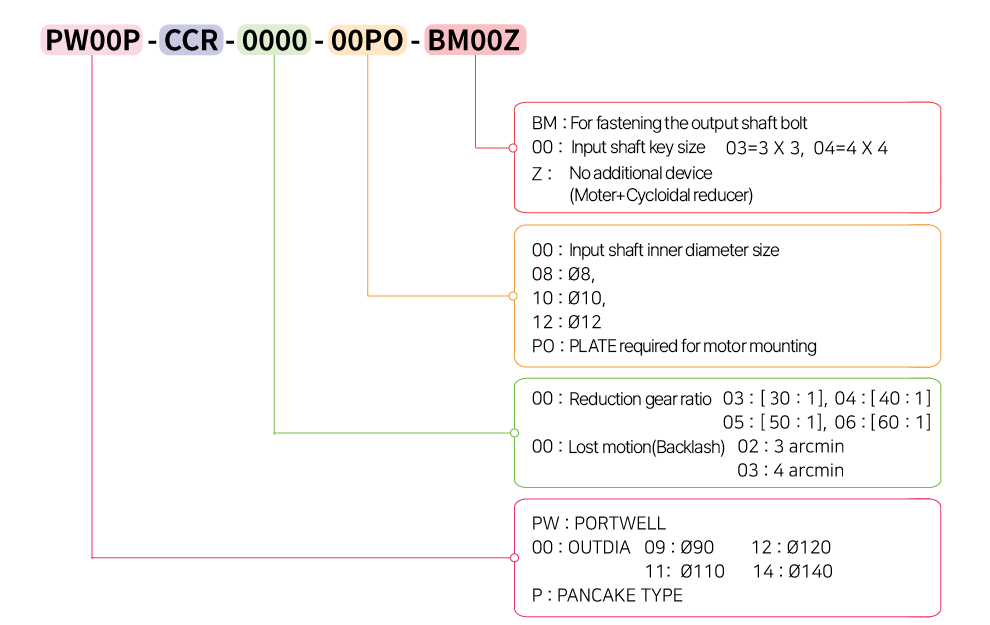
Order Example
PW09P-CCR-0302-08PO-BM03Z
The reducer has an outer diameter of Ø92, a reduction ratio of 30, a lost motion of 4 arcmin, and an input shaft (motor shaft outer diameter) of Ø8. If an additional PLATE is needed for motor mounting, please indicate in the PO. For the output shaft, use bolt fastening BM, and the input shaft key size is 3 x 3.
For PANCAKE TYPE, a FLANGE TYPE can be made available upon separate request after consultation.
However, the outer diameter dimensions must be changed.

Precautions for Using the CCR series
1. Installation Conditions (Operating Environment Conditions)
Do not use in enclosed spaces or areas where dust is generated.
Do not use in locations with flammable materials or where corrosive gases, vapors, or dust are present.
The reducer and motor are not waterproof, so they should not be exposed to liquids or submerged.
2. Operating Environment
Caution Temperature
-20 ◦C ~ 40◦C
Caution Environment
Do not use in areas exposed to rain or where water drips.
Do not use in places where condensation occurs due to rapid temperature changes.
When used outdoors, it is required to install in a separate storage location or have equivalent facilities.
Humidity
Use at 60% or lower humidity.
3. Other
Installation is prohibited in areas where excessive torque is applied (not suitable for the capacity).
Please familiarize yourself with the specifications of the reducer before use.